Extend the 3D stereo camera module of LG thrill phone P925
This is a quite interesting project which requires digging out the 3D stereo camera module from the LG thrill P925 smart phone and driving it somewhere outside the smart phone. What…? Sounds like put your eye balls miles away and… you are still able to see through them!
Is it possible?
– Of course yes, as long as you can extend the cable! Here is how I did it (with photos):
1. A brand new LG thrill P925, equipped with dual 5MP camera module that is capable of stereoscopic 3D capture:
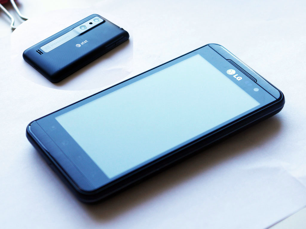
2. Take off the back and expose the pretty big 3.7V Li-Ion battery. Use #00 Phillips-head screwdriver to avoid stripping the screws:

3. Remove the speaker module. The speaker module is actually installed on top of the middle plastic frame that is protecting the mother board and such. So it needs to go first:
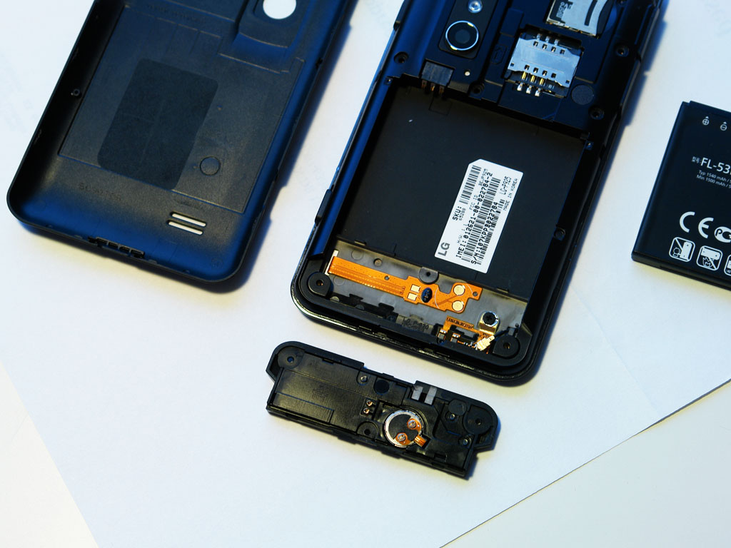
4. With the speaker module being removed, it is quite easy to remove the middle frame with just a little bit efforts:
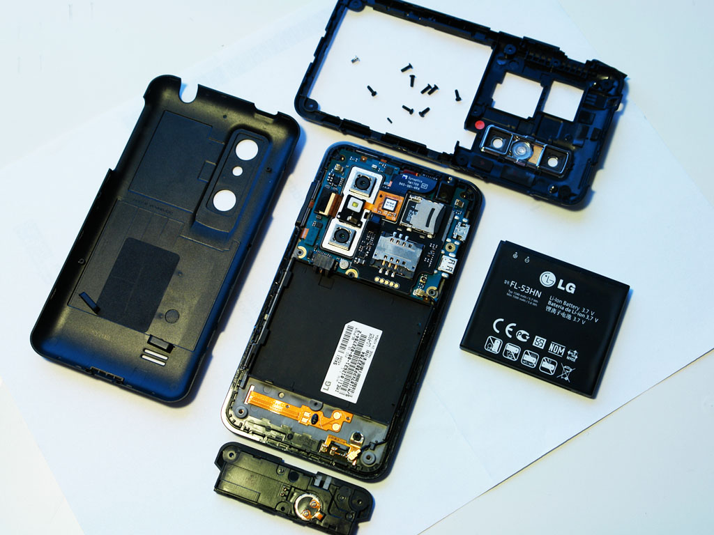
5. Under the middle frame goes the mother board and almost everything of interest. As you can see, the dual-camera module is vertically embedded into the circuit boards with FPC connector on the side. An LED flash is coming from the other side and being laid on top of the camera module, making advantage of its metal frame as heat sink. Looks like all I need to do is to dig out the camera module and then to make an extension cable for the FPC connector:
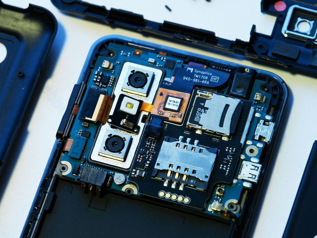
6. Flip up the flash and totally expose the camera module:
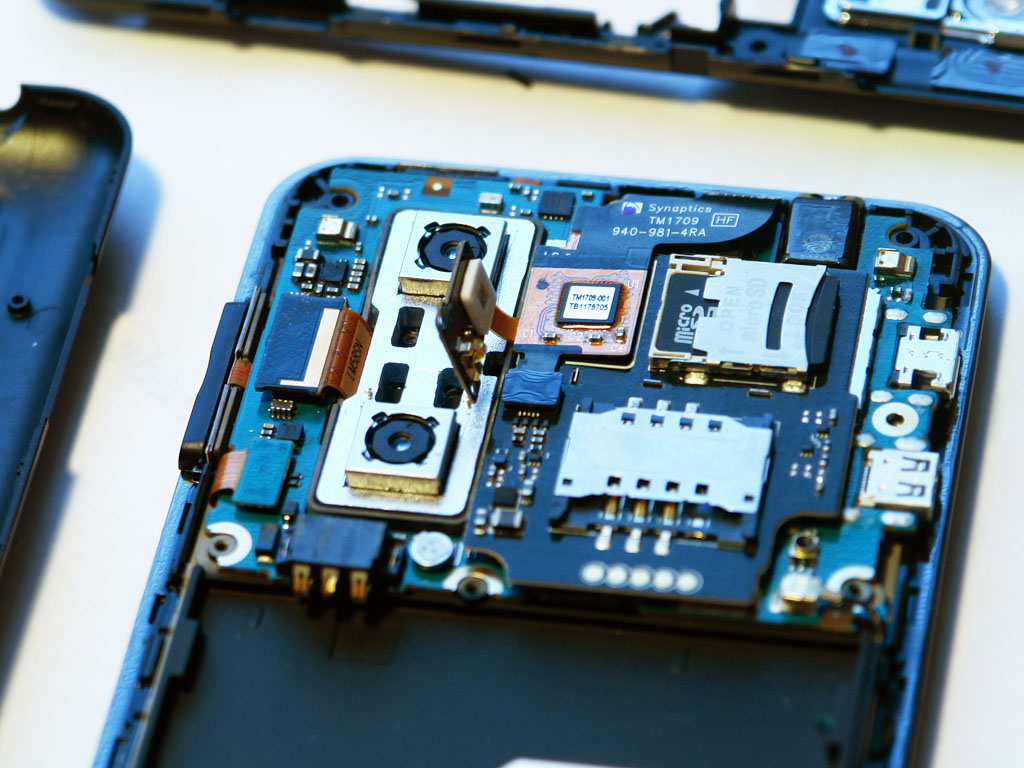
7. Pull out the camera module from its bed. This requires some efforts as the module is taped on its bottom and the outline fits the bed pretty tight.

8. Gently disconnect the FPC connector from the mother board and the camera module is completely separated:

9. Now I am facing the real challenge: how to make a cable with the connectors that mate with the ones on the phone mother board and the camera module. With some measurements, it is not difficult to find out that it’s a 40-pin, 0.4mm-pitch connector. If Digikey or some components distributor would carry the same products, things would be much easier. Unfortunately they don’t. I ordered all the available 40-pin, 0.4mm-pitch connectors but none of them fit the cell phone. After talking to the LG phone repair shop, I finally figured out its connector is “GB042-40S-H10-E3000” from LG. Apparently, this component is not that easy to get hold of.
Since it is almost impossible to buy the mating connectors, the next possible approach is to replace the original connectors with the ones available from Digikey. So I ordered several pairs of the connectors “DF40C-40DP-0.4V(51)” and “DF40C-40DS-0.4V(51)” from Digikey. Both are manufactured by Hirose.
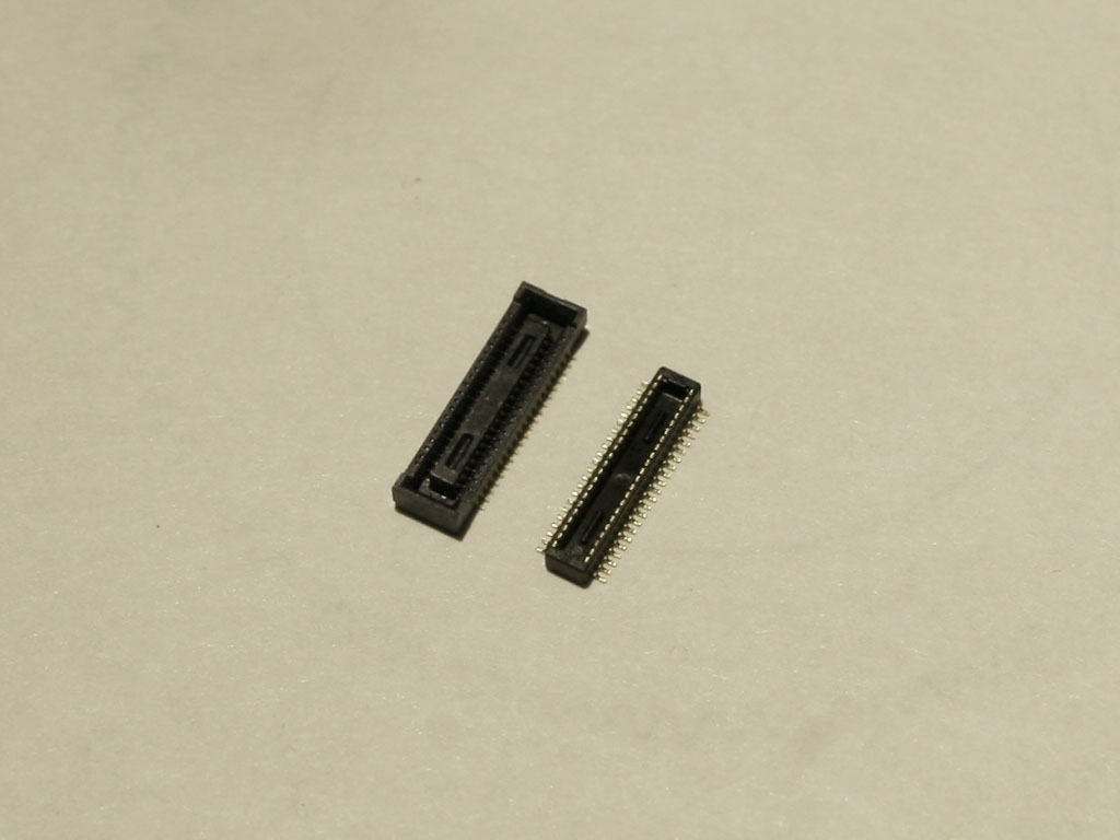
10. Replacing the 40-pin, 0.4mm-pitch connector is not non-trivial job. It requires some desoldering / soldering skills. I strongly recommend Chip Quick’s Removal Package “SMD1” for components removing. Here is the photo of the LG thrill when the camera module connector is remove from its mother board:

11. A closer look at the solder pad. Although I was doing this with extreme care, I still mistakenly wiped out one pad. I was just lucky as I later on figured out that this pin is for ground so it was fixable by jumping a wire to some nearby ground.

12. Soldering a new connector is considerably easier than removing. Here is the photo and a closer look when it is done:

13. Now the mother board has a new connector, so should the camera module.
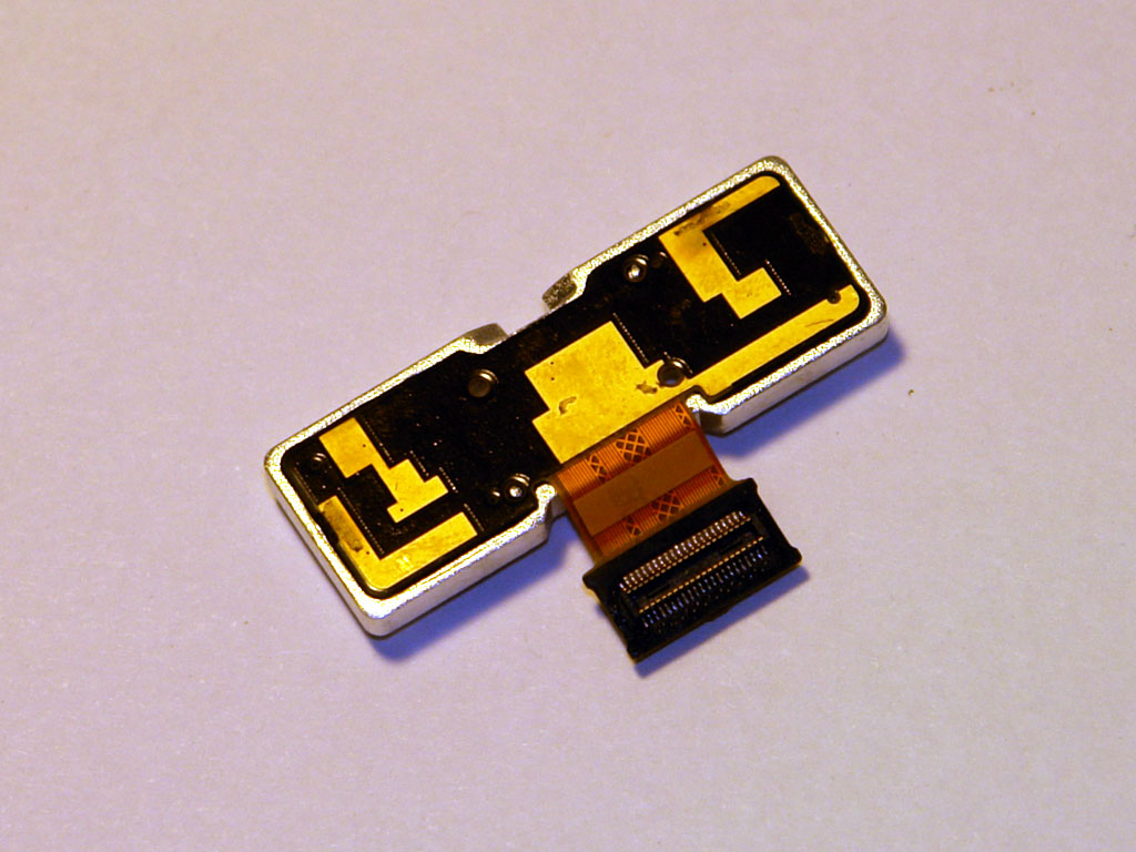
14.When both sides have been upgraded with the new connectors, a function test should be carried out before I move on to the cable part. Simply plug in the camera module back into the new socket and turn on the cell phone. Make sure everything still works after the replacement procedure.
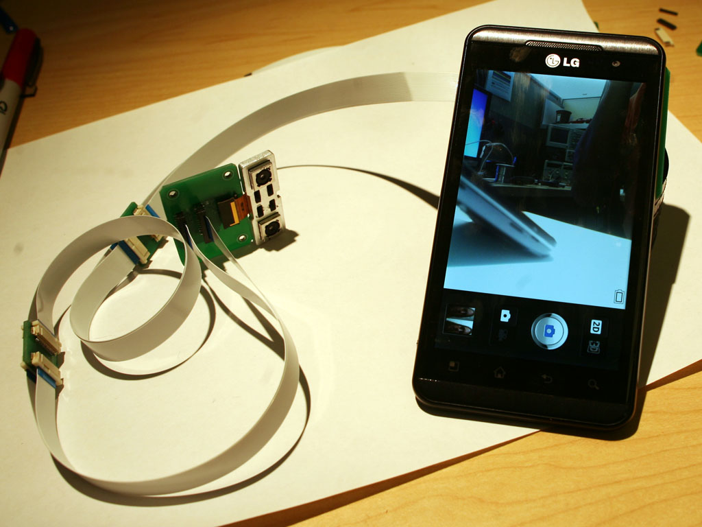
Next step towards the final “extension” goal is to literally make the extension cable. The FPC cable tailing on the camera module would be an ideal solution for the extension, but the cost is going to be an issue. For this prototype, I decided to make low cost circuit boards as the adapter.
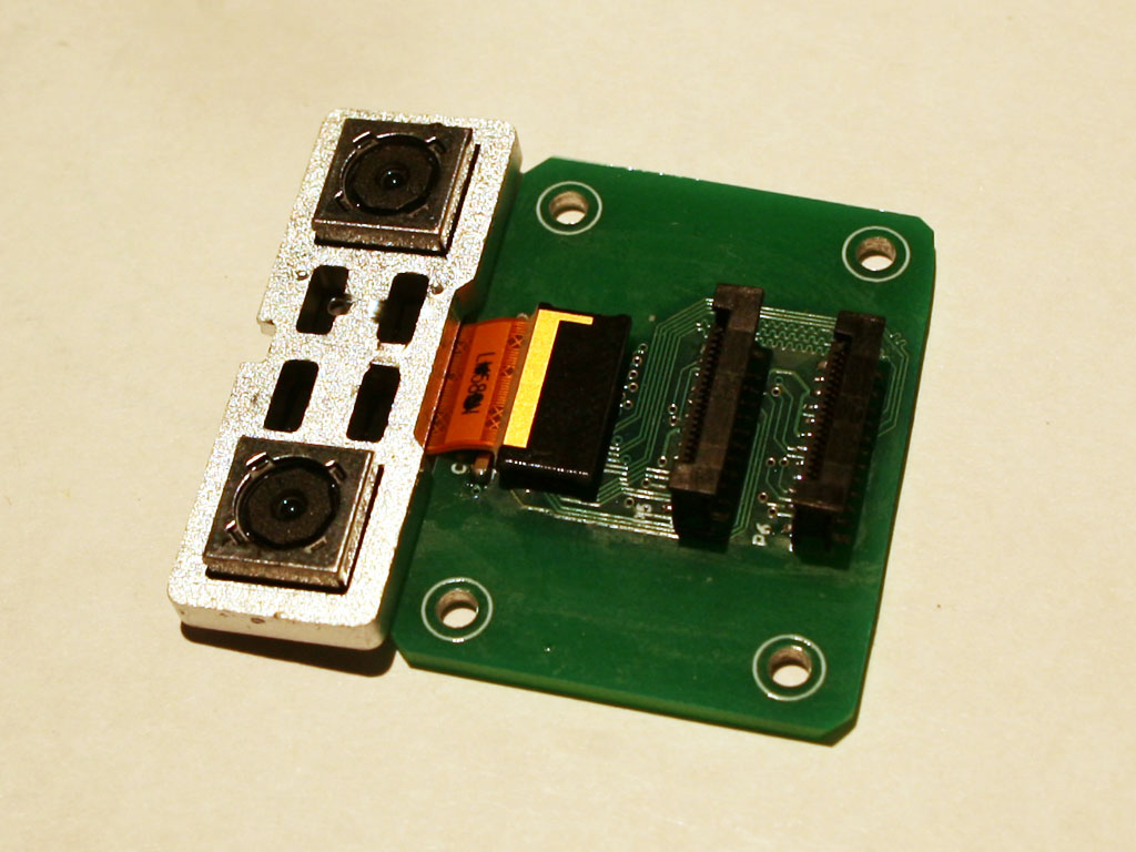
Adapter board for camera module:
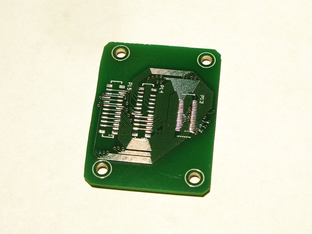
Adapter board for mother board:
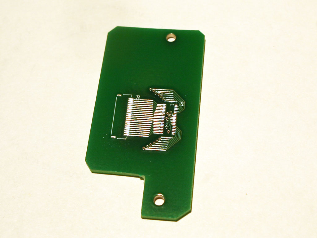
15. Solder connectors on the mother board side adapter, and the finished board looks like:
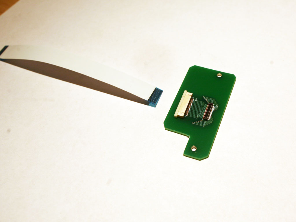
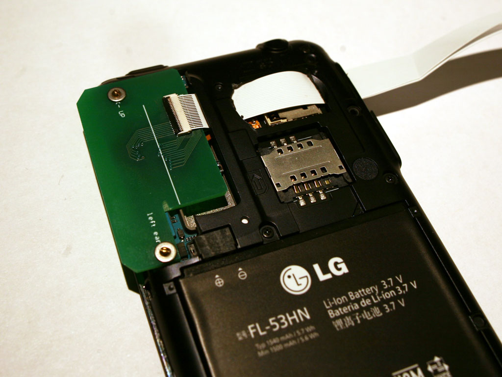
16. After the adapter is finished, plug into the mother board and tighten the screws to the phone body. Since the PCB is little big, I had to trim off the inner plastic frame to make it fit. White cables are 0.5mm-pitch, 20-conductor FPC jumper ordered from Arrow. FPC BackFlip™, Easy-On™ connectors are from Digikey.
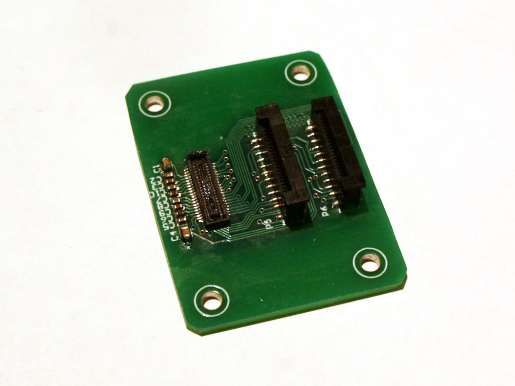
17. Then finish the camera-side adapter. The vertical FPC connectors are from Digikey. As shown on the left side of the picture below, there are a series of bypass capacitors being mounted close to the camera connector. These bypass capacitors are critical for the extension to work since the camera module is a high-speed digital device requiring large current to switch between logic low and high at high frequency. Bypass capacitors work as energy storage to supply the surging current and avoid voltage drop, which will cause the device failure. When the camera module is extended away from the mother board, it also leaves its “energy storage” on the mother board. So some local bypass capacitors are required on the adapter board.
18. Everything is ready for the final assembly. Make sure cables are connected tightly and turn on the phone. The camera module is working outside the body now!
Here is the final application for this project:
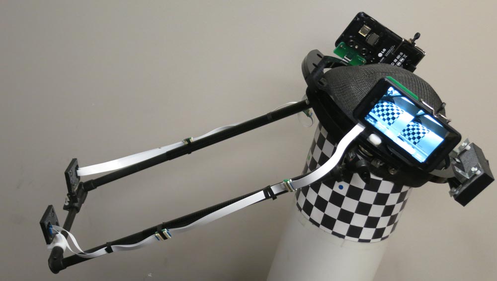
A Cell Phone Based Platform for Facial Performance Capture. (http://gl.ict.usc.edu/Research/CellHeadCam/)

That is very awesome – good job! You inspired me to get a used p925 to mess with the dual cameras in opencv. In looking at the poster you linked at the end, you (or someone on your team) mention fixing the convergence of the cameras via the lg Real3D SDK. What code fragment does this? I am having trouble finding detailed documentation on the SDK.
Thanks for your attention. I’ve forwarded your question to our researcher and hopefully she will respond your question.
can you guys please release the app? I want to try out using VR on my android phone, but I just started with the android sdk and as such cannot make a program like this myself.
Hi, i really liked your post. It made me start my own project where I want to use phone and stereo cameras to drive a robot. Since I’m not an electrical engineer, I’m not quite sure how to do the adapter part. On the board for camera module do you just connect one side of the connector (20 pins) to first vertical connector and other side (other 20 pins) to second vertical connector? How do you connect the capacitors (do they go just from one side)? Is it the same for mother board board? Any help would mean a lot, thank you very much.
Yes, it is literally a one-to-one mapping. For the capacitor, I was basically copying the way they are bypassing the power and ground on the mother board.
Thanks for your reply.
I’m still struggling with this adapter. Is there an another way to do this without it? What about this FPC cable from camera, can I use one without an adapter? In case I can, do you maybe know where can I buy one (since you mentioned that it is expensive)? In case I can’t, is it possible by any chance to get some more information (or some kind of files) on how to make the circuit boards? Thank you very much once again.
As long as you can extend the connection from the camera module to the mother board, you don’t necessarily need the adapter. It is just the way I was doing it. And I don’t think you can buy it since it is very customized.
Hi again and thanks a lot for the help. I have one more question. I made the board as you said (one to one mapping) but unfortunately it doesn’t work. Are there some details that I should take particular note of (like length of the trace)? I see that you also had 2 boards (3rd and 8th image from the end) and that second one is a bit different (it has this “snake” like traces). For which pins do you use this kind of trace (I assume 1,2 and 19,20)?
Thanks again!
Hi there, thanks for your message. I forgot which pin(s) require trace length tuning (the snake-like trace), but I strongly suggest doing so because it is one of the key elements that make high-speed circuits work. Another important factor is that you should place by-pass capacitors close to the camera module, especially when the extension cable is long. Good luck!
Im not capable of doing this my self, I will buy this phone with that set up off of you and pay w.e shipping charges are! Please contact me at sunnysdosanjh@gmail.com
How can i purchase the LG-P925 battery in the philippines.
This is really cool! I am currently trying to replicate your work. Would you tell me what kind of bypass capacitors are you using? Thanks!
Ceramic capacitor will do the job. 0.1uF ~ 47uF is preferred.
Thanks a lot!
Hi there, this is an incredible little project! I have a question regarding the stereo module that you removed from the phone: Would it be possible to use the module and interface it with say raspberry pi? I have a project that I’d really like to use a phone camera module (non stereo) with but the ribbon cable element makes it really difficult to figure out how to interface with the camera. Thanks and good work!
I don’t quite think it is possible without the module’s spec and datasheet. Even I can figure out which wire is power which is signal, there is still no way to reverse-engineer the communication protocol.
Has anyone been successful to do this with any iphone ?
Hello. I am decided to repeat your project but I have some problems.
The first problem is connected with capacitors. My LG P700 has no capacitors which work as energy storage for a camera module. I think to add this capacitors like on the scheme https://www.dropbox.com/s/0h6csjnnvanzspw/P700-P925.png?dl=0
Also I want to know what did you do with capacitors on mother board? Have you just deleted it?
I didn’t touch those on the mother board.
Could an android endoscope inspection scope cable work?
https://www.google.com/?gws_rd=ssl#q=cell+phone+with+cable+scope+camera+adapter&tbm=shop&spd=3993812416206449278
could the android version of the endoscope/inspection scope cable system work(scroll down to $10.95 version on the link.
https://www.google.com/?gws_rd=ssl#q=cell+phone+with+cable+scope+camera+adapter&tbm=shop&spd=3993812416206449278
I don’t know what you are asking, or what this has anything to do with my blog. But yes, the scope you referred to will work if you have a compatible android phone after you install the app.
can this work on the samsung phone like j series ? how could i extend the camera module and from where should i get this extension cable
You will have to make your own extension cable. I won’t say it’s impossible to make this work on the samsung phones, but you will have to try.
hi XueMing, I see that you still reply to comments. Any way that you have done it with newer phone models? And may I ask if you are willing to replicate a model and sell it to me?
Hi Michael! Thanks for visiting my blog. I haven’t done it with any newer models ever since. And I don’t think the same LG phone is still on the market…….
Hi, I am planning to do this. any idea what is the maximum length of cable i can use for this purpose as i have heard extending cable will make the camera stop working
There is no guarantee for the extension cable to work, and there is no global number for the max cable length. All the variants, including image sensor; signal protocol; data rate will contribute to the final result. It is getting harder and harder to re-produce this work on the latest hardware.
where can i get the little boards for connectors
It was custom made, and only worked for this phone model.
Would you mind publish the layout?
Hey. Thank you for your article.
I successfully reproduced your project.
https://youtu.be/evcpW-UT2E4
Congrats! It’s awesome!
btw, how did you find out that pin you removed was GND?