Synchronize multiple Canon Rebel T4i video shooting with reverse-engineered RC-6 protocol
Let’s first take a look at the video clip of how my customized remote synchronize two (or more) Canon Rebel T4i video shooting.
Canon Rebel series latest model T4i (as well as older T3i, T2i) came with a dedicated video button that allows easy start/stop of video shooting. This is a very useful button as you don’t have to go through the complex menu to shoot a movie. This handy function, however, becomes a major obstacle when professional photographers, computer graphics/vision researchers try to build multi-camera rigs for video capture with this model. Unlike much more expensive models such as Canon 1D mark IV or 1DX that allow users to map the video start/stop function onto its shutter button, T4i doesn’t seem to support migratable movie button. When you need to start or stop more than one T4i’s video capture within strict timing contraints, the mission seems to be impossible, not to memtion that camera drifts when button is pressed.
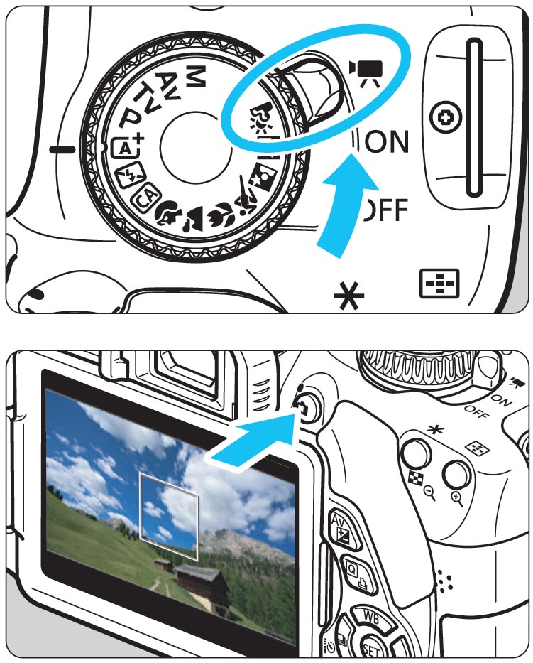
A normal way to operate a video capture: 1. Set the power switch to “Movie” mode; 2. Press the move button to start/stop.
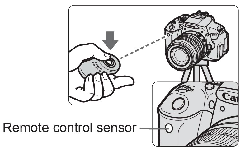
According to its official instructions, T4i does provide an alternative way to control the video capture with the wireless RC-6 remote.
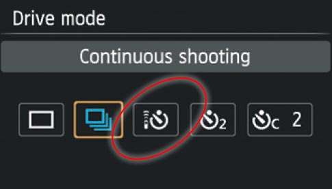
RC-6 is basically an infrared emitter that sends signal under specific protocol to the camera sensor. If the protocol is recognized by T4i, the camera will do the jobs accordingly. In order to use the RC-6 remote, the camera must be enabled to allow the remote control.
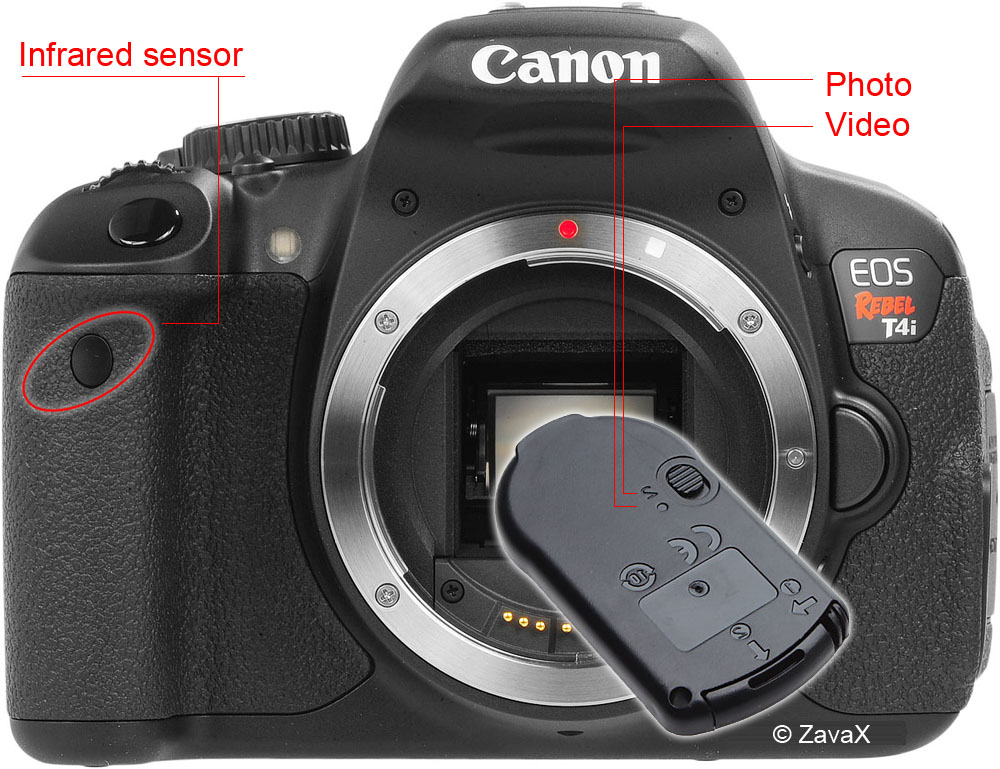
The camera is set to receive IR signal for remote control when the icon in the red circle is selected. This will allow the camera to fire static shot if RC-6 is configured at “o” position, or to shoot a video at “2” position. Below is the illustration of a RC-6 remote.
Since infrared signal is very directionally sensitive, the RC-6 remote must be pointed at the sensor for reliable communication. Just like a TV remote, it won’t work if you are too far away or not pointing at the right place. Now let’s go back to the multi-camera rig that you need to trigger with the remote, if they happen to be mounted in a configuration that 1) all of the cameras are facing the same way; and 2) they can be reached at a not-too-far-away distance, then I am sure one RC-6 will do the job just fine. Otherwise, you will have to equip each T4i with a RC-6 and find a way to press all the remotes at the same time — which doesn’t seem to be a lot better than pressing the buttons on the camera.
There are some discussion about running fiber-optics from the remote’s IR emitter to somewhere close to the camera’s sensor, so that the infrared signal could be split and transmitted towards different cameras. I feel a little bit skeptical about this as the fiber-optics might be too thin to carry the infrared light strong enough for the camera sensors. So, here comes my ultimate solution: Let’s find out what exactly RC-6 is transmitting (reverse engineer) and reproduce it in front of every T4i IR sensor.
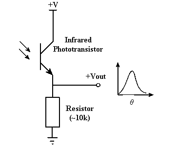
In order to read the IR signal from RC-6, we will need a photodiode (usually faster than phototransistor) and a working circuit. Search google for “IR sensor circuit”, you will end up having a whole bunch of schematics. The following one is what I built to read the RC-6: very simple, one photodiode and one 10K ohm resistor, hooked up to a 5VDC power supplier.
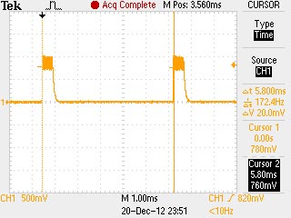
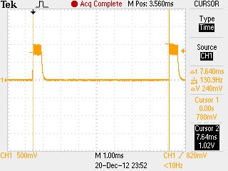
Then connector your oscilloscope probe to “+Vout”, the followings are the waveform of the IR signal from RC-6 after I pressed the button:
Snap shots of oscilloscope: PD response of RC-6 remote with switch on “2” (left) and “0” (right) configuration.
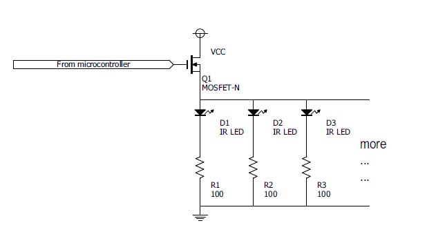
At first glance, it looks like two pulses generated about 5.8ms apart for video capture and 7.64ms for still photo. It won’t be too hard to implement this with a microcontroller: I am using my PIC32-base (PIC32MX795F512L) RTM platform, IR LED (SFH 4545)and NMOS (DMN2400UV-7) switch. Schematic shows as below:
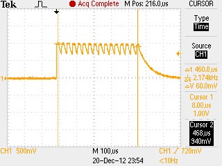
Unfortunately, it doesn’t work~~~~~~~~~ even after I am 100% sure that everything works just as they should. So I looked into the above oscilloscope snap shots to find if there is anything I am missing. The only thing I don’t feel very comfortable with is the noise (oscillating signals) on top of the pulse. Usually it should be flat if the signal is clean. After zooming into the width of the pulse, I figured out the noise actually turned out to be something periodic:
Instead of one big and wide pulse, it look like it is composed of many short pulses with much higher frequency, whereas their falling slopes are too slow to reach zero. This reminds of the fact that the IR detector circuit I am using with one photodiode and one resistor in series is notorious for slow response! If this is true, I can conclude that the RC-6 transmits 16 pulses @33.33KHz (or 30us apart) in a row, wait for about 5.32ms, and transmit another 16 pulses again. For static shot, replace the 5.32ms with 7.16ms.
The result: it works!
I can explain those pulses. What is done in infrared remotes (not just the RC-6 but also TV and other remotes) is a carrier signal roughly between 30 and 60 kHz is used in bursts to represent information – that is, instead of sending a single pulse to represent logic high, it sends a burst at 33kHz or whatever the chosen carrier frequency is. What this allows is much better noise rejection on the receive side. There’s IR noise all over the place from the sun, indoor lighting, heat sources, etc, but typically it will not be concentrated at any particular frequency, at least not in the tens of kHz. You can use a receiver IC like these from Vishay (http://www.vishay.com/ir-receiver-modules/). What they do is first filter out non-IR optically, then bandpass filter the output of the phototransistor so that the 33kHz signal (or whatever carrier is used) is the only thing strong enough to register. It then simply outputs logic low when it sees the carrier and high when it does not (the output is active low).
Great explanation! Thanks Ben!
Nice planing to try out this
When recording a hd video can u put a way of reverse to the camera so that the items you show don’t appear backwards please let me know email me
post your code please
The phototransistor is much faster with lower resistance value …it might reduce the signal level, but not a problem for your oscilloscope.