How to rework high density package ICs with DIY reflow oven
I am working on a DIY PCB project that requires mounting three PICOR PI3301 Power regulators. Unfortunately, the PI3301 comes with a high density 123-pin LGA footprint in a 10mm x 14mm package. Furthermore, three of them will need to work in a synchronized close-loop configuration to yield high current output. That is to say, the power module won’t work efficiently unless all of the three DC-DC buck converters are properly soldered. How can I accomplish this with my re-flow oven?
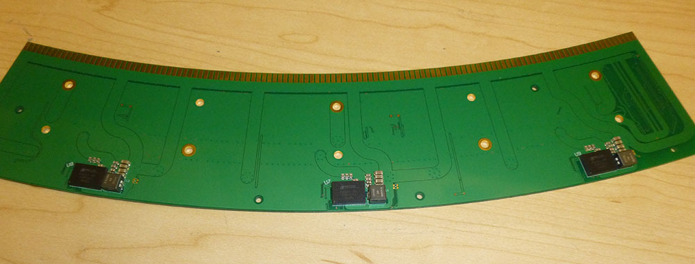
My re-flow oven has been part of my workbench tool team for more than a year, and I had successfully re-flowed a variety of electrical components, as small as 2mm-wide the Philips Rebel Z LED. However, re-flow of a dense package IC such as LGA (or BGA) is something I have never tried before. So I carefully prepared the stencil, applied the paste, placed the components, and Baked! Here is what I got from my oven:

Everything looked perfectly fine from outside. However, you just couldn’t tell if each 123 pads are correctly soldered without an X-ray. So I loaded the power module with dummy resistors to stress test the power supplying. After about 5 minutes, here was what I could tell:

The left two were getting warm; the one on the right stayed cool. Apparently the cool one is not functioning, most likely caused by bad re-flowing. So how can I fix it without affecting the left two that seemed to be working correctly? Or, how can I partially re-heat the right side of the board and re-flow again? Here is what I came up with:


Apparent this is not a cool way of using an oven, but it works! Only the right side of the circuit board is inside the oven. Some PCB scrap and metal sheet were used in replacement of a “door” to cover the opening. Surprisingly, the oven heated up the board really well.
All I needed to do was to wait until my PID thermal controller heated up the board till 230°C, and then SHAKE it! Since the solder on the right side of the board was being melt under this high temperature, the components easily fell off.
Simply clean the solder pad with solder wick and we will be ready to re-flow it back.
Now it is ready for the oven again. I only re-flowed the right side of the board the same way as I did to knock off the bad-soldered components. After about 4 minutes, here is what I got from the oven:
And the final test showed that all of the three buck converter chips warmed up after several minutes of dummy load test. So I successfully fixed (remove & re-solder) the board by partially re-flowing the PCB.


