Understand addresses in Microchip’s 16-bit MCU and its translation to Intel Hex32 format
Unlike most of the RISC architecture which utilizes the same map and bus for both data and instruction space, the Microchip’s 16-bit MCUs, such as the PIC24 and the dsPIC33 series (dsPIC30, dsPIC33E, dsPIC33C), implemented so call “enhanced Harvard architecture” with 16-bit wide data and 24-bit wide instruction format. That immediately explains why it has separate buses for data and instructions — width is different. In addition, their implementation details differ a lot. I will go through them and focus on how the address system work on the MCU’s hardware and software level.
24-bit wide address for program memory. According to Microchip’s DS70005156, it is more appropriate to think of each address of the program memory as a lower and upper word. Since each word is 16-bit, two words add up to 32-bit. Microchip didn’t implement the upper byte of the upper word — which they call the “phantom” byte. As a result, the higher 8-bit and the lower 16-bit make it a 24-bit wide space for instruction.
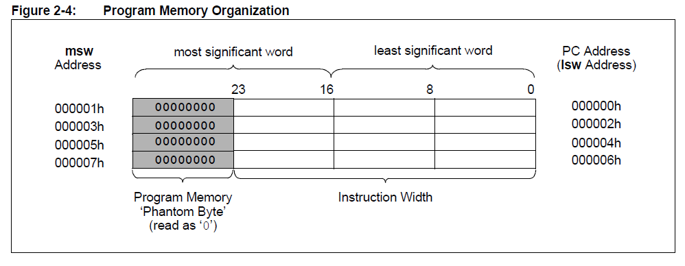
Either the higher 8-bit byte or the lower 16-bit word has its own address, as you can see from the figure 2-4. However, the higher word address (odd value) is useless because each instruction is 24-bit wide, and the PC (program counter) is only aligned to the lower word, which is always even number. With that being said, when PC moves onto next instruction in the sequential order, the address is actually incremented by 2!
16-bit wide address for data memory. According to Microchip’s DS70595C, PIC24/dsPIC33’s data memory is implemented differently from the program memory – it is only 16-bit wide. The data memory is used for all the internal registers (SFRs) and data space (RAM).
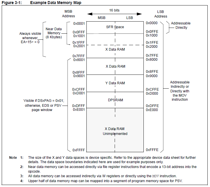
As you can see from the Figure 3-1, the higher byte and lower byte of data memory have their own address, that is to say, data memory address works more like RISC system — each single byte has its own address. And more importantly, they are individually addressable.
PIC24/dsPIC33 are 16-bit MCU, so their data is 16-bit wide by default. In order for the instructions to work with 8-bit data (which is still quite common when dealing with 8-bit peripherals such as UART or SPI), data variables can be accessed as 8-bit or 16-bit, thanks to the address transparency of the bus design.
Now we understand how 16-bit PIC24/dsPIC33 architects its bus and address. Follow this post for more details regarding how to parse their binary hex codes.